


Bonjour à tous,
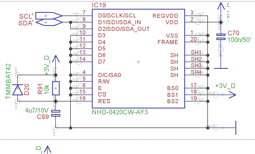
J'utilise un afficheur oled NHD-0420CW-AY3 donc de la marque Newhaven Display, l'afficheur est composé de 4 lignes de 20 caractères. Doc : https://www.newhavendisplay.com/spec...0420CW-AY3.pdf
Le nom du driver utilisé pour mon afficheur est US2066. Doc : http://www.newhavendisplay.com/app_notes/US2066.pdf
Le microcontrôleur que j'utilise dans mon code est un STM32F107RC. Doc : http://www.st.com/content/ccc/resour...CD00220364.pdf
Cet afficheur est connecté sur le bus I²C du microcontrôleur.
Mon objectif est de ne pas utiliser arduino.
Ci-dessous le schéma de mon afficheur :
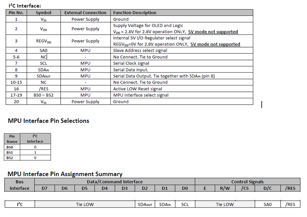
On peut voir que par rapport à la doc la configuration en mode i2c est correct :
J'ai ensuite récupérer et adapter un code pour faire fonctionner mon afficheur, oledDisplay.c :
Code : Sélectionner tout - Visualiser dans une fenêtre à part
2
3
4
5
6
7
8
9
10
11
12
13
14
15
16
17
18
19
20
21
22
23
24
25
26
27
28
29
30
31
32
33
34
35
36
37
38
39
40
41
42
43
44
45
46
47
48
49
50
51
52
53
54
55
56
57
58
59
60
61
62
63
64
65
66
67
68
69
70
71
72
73
74
75
76
77
78
79
80
81
82
83
84
85
86
87
88
89
90
91
92
93
94
95
96
97
98
99
100
101
102
103
104
105
106
107
108
109
110
111
112
113
114
115
116
117
118
119
120
121
122
123
124
125
126
127
128
129
130
131
132
133
134
135
136
137
138
139
140
141
142
143
144
145
146
147
148
149
150
151
152
153
154
155
156
157
158
159
160
161
162
163
164
165
166
167
168
169
170
171
172
173
174
175
176
177
178
179
180
181
182
183
184
185
186
187
188
189
190
191
192
193
194
195
196
197
198
199
200
201
202
203
204
205
206
207
208
209
210
211
212
213
214
215
216
217
218
219
220
221
222
223
224
225
226
227
228
229
230
231
232
233
234
235
236
237
238
239
240
241
242
243
244
245
246
247
248
249
250
251
252
253
254
255
256
257/* * Afficheur Oled connecté sur le bus I2C du µC * pins SDA(PB7) et SCL(PB6) du µC * * Pins SDA 8 et 9(D1/SDI/SDA_IN et D2/SDO/SDA_OUT) et * Pins SCL 7 (D0/SCLK/SCL) * du composant IC19(sheet 6) NHD-0420CW-AY3 */ /* The circuit: * * OLED pin 1 (Vss) pin ground * OLED pin 2 (VDD) pin 3.3V * OLED pin 3 (REGVDD) to Vss ground * OLED pin 4 (SA0) to Vss ground (to assign I2C address 0x3D, connect to VDD 3.3V) * OLED pin 5 and 6 to Vss ground * OLED pin 7 (SCL) pin SCL (7=D0) * OLED pin 8 and 9 (SDAin,SDAout) pin SDA (9=D2; 8=D1) * OLED pin 10 to 15 to Vss ground (14=D7; 13=D6; 12=D5; 11=D4; 10=D3) * OLED pin 16 (/RES) pin Reset or VDD 3.3V * OLED pin 17 (BS0) to Vss ground * OLED pin 18 (BS1) to VDD 5V * OLED pin 19 (BS2) to Vss ground * OLED pin 20 (Vss) to Vss ground */ /**********************/ /****** includes ******/ /**********************/ #include "oledDisplay.h" /*********************/ /****** globals ******/ /*********************/ /** @brief Number of display rows */ const uint8_t ROW_N = 4; /** @brief Number of display columns */ const uint8_t COLUMN_N = 20; /** @brief pin assigned to the Reset line (optional, can be always high) */ const uint8_t RES = 16; /** @brief Display I2C Slave address, in 7-bit form: 0x3C if SA0=LOW, 0x3D if SA0=HIGH */ const uint8_t SLAVE2W = 0x3C; /** @brief Strings to be displayed */ const uint8_t TEXT[4][21] = {"1-Newhaven Display--", "2-------Test--------", "3-16/20-Characters--", "4!@#$%^&*()_+{}[]<>?"}; /** @brief DDRAM address for each line of the display */ uint8_t new_line[4] = {0x80, 0xA0, 0xC0, 0xE0}; /** @brief Display mode: 1/3 lines or 2/4 lines; default 2/4 (0x08) */ uint8_t rows = 0x08; /** @brief Packet to be transmitted (max 20 bytes) */ uint8_t tx_packet[MAXPACKET]={0}; //uint8_t tx_packet[]={0x00,0x00,0x00,0x00,0x00,0x00,0x00,0x00,0x00,0x00,0x00,0x00,0x00,0x00,0x00,0x00,0x00,0x00,0x00,0x00}; /*********************************/ /****** Function definition ******/ /*********************************/ /** * @brief subroutine: prepares the transmission of a command * * @param[in] commandByte The command to be executed by the display */ void command(uint8_t commandByte) { i2cBuffer[0] = DATABYTE_COMMAND; // Control Byte; C0_bit=0, D/C_bit=0 -> following Data Byte contains command i2cBuffer[1] = commandByte; send_packet(2, i2cBuffer); // Transmits the two bytes } /** * @brief subroutine: prepares the transmission of a byte of data * * @param[in] dataByte The character to be displayed */ void data(uint8_t dataByte) { i2cBuffer[0] = DATABYTE_DATA; // Control Byte; C0_bit=0, D/C_bit=1 -> following Data Byte contains data i2cBuffer[1] = dataByte; send_packet(2, i2cBuffer); // Transmits the two bytes } /** * @brief subroutine: send to the display the number of bytes stored in tx_packet * * @param[in] byteStored Command or bytes of data stored * @param[in] *tx_pack Packet to be transmitted */ void send_packet(uint8_t byteStored, uint8_t *tx_pack) { /* Wire.beginTransmission(SLAVE2W); */ // Begin the transmission via I2C to the display with the given address /*send start condition and slave address, then send the data and stop condition */ i2cmWrite(SLAVE2W, byteStored, tx_pack); /* Wire.write(tx_packet[index]); */ // queue bytes for transmission /* Wire.endTransmission(); */ // Transmits the bytes that were queued } /** * @brief subroutine: displays the four strings, then the same in reverse order */ void output(void) { uint8_t row = 0; // Row index uint8_t column = 0; // Column index command(CLEARDISPLAY); // Clears display (and cursor home) softDelay(2); // After a clear display, a minimum pause of 1-2 ms is required for (row=0; row<ROW_N; row++) // One row at a time { command(new_line[row]); // moves the cursor to the first column of that line for (column=0; column<COLUMN_N; column++) // One character at a time { data(TEXT[row][column]); // displays the corresponding string } } softDelay(200); // Waits, only for visual effect purpose for (row=0; row<ROW_N; row++) // One row at a time { command(new_line[row]); // moves the cursor to the first column of that line for (column=0; column<COLUMN_N; column++) // One character at a time { data(TEXT[3-row][column]); // displays the correspondig string (in reverse order) } } } /** * @brief subroutine: fills the entire display with the character "block" */ void blocks(void) { uint8_t row = 0; // Row index uint8_t column = 0; // Column index command(CLEARDISPLAY); // Clear display (and cursor home) softDelay(2); // After a clear display, a minimum pause of 1-2 ms is required for (row=0; row<ROW_N; row++) // One row at a time { command(new_line[row]); // moves the cursor to the first column of that line for (column=0; column<COLUMN_N; column++) // One character at a time { data(SEGCONFIGURATION); // displays the character 0xDB (block) softDelay(50); // Waits, only for visual effect purpose } softDelay(200); // Waits, only for visual effect purpose } } /** * @brief initial setup */ void setup(void) { softDelay(10); // Waits 10 ms for stabilization purpose if (ROW_N == 2 || ROW_N == 4) rows = 0x08; // Display mode: 2/4 lines else rows = 0x00; // Display mode: 1/3 lines command(FUNCTIONBLINK | rows); // Function set: extended command set (RE=1), lines # command(FUNCTIONSELECTA); // Function selection A data(0x5C); // enable internal Vdd regulator at 5V I/O mode (def. value) (0x00 for disable, 2.8V I/O) command(FUNCTIONLINE | rows); // Function set: fundamental command set (RE=0) (exit from extended command set), lines # command(DISPLAYCTRL); // Display ON/OFF control: display off, cursor off, blink off (default values) command(FUNCTIONBLINK | rows); // Function set: extended command set (RE=1), lines # command(OLEDCHARACTERIZ_SD); // OLED characterization: OLED command set enabled (SD=1) command(DISPLAYSET); // Set display clock divide ratio/oscillator frequency: command(0x70); // divide ratio=1, frequency=7 (default values) command(OLEDCHARACTERIZ); // OLED characterization: OLED command set disabled (SD=0) (exit from OLED command set) if (ROW_N > 2) command(FUNCTIONSET_N); // Extended function set (RE=1): 5-dot font, B/W inverting disabled (def. val.), 3/4 lines else command(FUNCTIONSET); // Extended function set (RE=1): 5-dot font, B/W inverting disabled (def. val.), 1/2 lines command(ENTRYMODESET_C); // Entry Mode set - COM/SEG direction: COM0->COM31, SEG99->SEG0 (BDC=1, BDS=0) command(FUNCTIONSELECTB); // Function selection B data(0x0A); // ROM/CGRAM selection: ROM C, CGROM=250, CGRAM=6 (ROM=10, OPR=10) command(OLEDCHARACTERIZ_SD); // OLED characterization: OLED command set enabled (SD=1) command(0xDA); // Set SEG pins hardware configuration: command(0x10); // alternative odd/even SEG pin, disable SEG left/right remap (default values) command(FUNCTIONSELECTC); // Function selection C: command(0x00); // internal VSL, GPIO input disable command(CONTRASTCONTROL); // Set contrast control: command(0x7F); // contrast=127 (default value) command(PHASELENGHT); // Set phase length: command(0xF1); // phase2=15, phase1=1 (default: 0x78) command(0xDB); // Set VCOMH deselect level: command(0x40); // VCOMH deselect level=1 x Vcc (default: 0x20=0,77 x Vcc) command(OLEDCHARACTERIZ); // OLED characterization: OLED command set disabled (SD=0) (exit from OLED command set) command(FUNCTIONLINE | rows); // Function set: fundamental command set (RE=0) (exit from extended command set), lines # command(CLEARDISPLAY); // Clear display softDelay(2); // After a clear display, a minimum pause of 1-2 ms is required command(SETDDRAMADDR); // Set DDRAM address 0x00 in address counter (cursor home) (default value) command(DISPLAYCTRL_D); // Display ON/OFF control: display ON, cursor off, blink off softDelay(250); // Waits 250 ms for stabilization purpose after display on if (ROW_N == 2) new_line[1] = 0xC0; // DDRAM address for each line of the display (only for 2-line mode) } /** * @brief clear display */ void clearDisplay(void) { command(CLEARDISPLAY); // Clears display (and cursor home) } /** * @brief display on */ void displayON(void) { command(DISPLAYCTRL_DCB); // Set the display/cursor/blink ON } /** * @brief display off */ void displayOFF(void) { command(DISPLAYCTRL); // Set the display/cursor/blink OFF } /** * @brief main program */ void mainOledDisplay(void) { i2cmInit(); // Initialize the I2C master setup(); // Initial setup displayON(); // Set the display ON output(); // Execute subroutine "output" softDelay(100); // Waits, only for visual effect purpose blocks(); // Execute subroutine "blocks" softDelay(100); // Waits, only for visual effect purpose displayOFF(); // Set the display OFF gpioSetLedTxd(FALSE); }
oledDisplay.h :
C'est donc bien sur la fonction mainOledDisplay qui sera lancé en première.
Code : Sélectionner tout - Visualiser dans une fenêtre à part
2
3
4
5
6
7
8
9
10
11
12
13
14
15
16
17
18
19
20
21
22
23
24
25
26
27
28
29
30
31
32
33
34
35
36
37
38
39
40
41
42
43
44
45
46
47
48
49
50
51
52
53
54
55
56
57
58
59
60
61
62
63
64
65
66
67
68
69
70
71
72
73
74
75
76
77
78
79
80
81
82
83
84
85
86
87
88
89
90
91
92
93
94
95
96
97
98
99
100
101
102
103
104
105
106
107
108
109
110
111
112
113
114
115
116
117
118
119
120
121
122
123
124
125
126
127
128
129
130
131
132
133
134
135
136
137
138
139
140
141
142
143
144
145
146
147
148
149
150
151
152
153
154
155
156
157
158
159
160
161
162
163
164
165
166
167
168
169
170
171
172
173
174
175
176
177
178
179
180
181
182
183
184
185
186
187
188
189
190
191
192
193
194
195
196
197
198
199
200
201
202
203
204
205
206
207
208
209
210
211
212
213
214
215
216
217
218
219
220
221
222
223
224
225
226
227
228
229
230
231
232
233
234
235
236
237
238
239
240
241
242
243
244
245
246
247
248
249
250
251
252
253
Voici un fichier source/header de plusieurs fonctions i2c codé par un collègue de plus haut niveau que les bibliothèques I2C dont je dois me servir pour utiliser l'i2c pour mon afficheur, i2cMaster.c :
Code : Sélectionner tout - Visualiser dans une fenêtre à part
2
3
4
5
6
7
8
9
10
11
12
13
14
15
16
17
18
19
20
21
22
23
24
25
26
27
28
29
30
31
32
33
34
35
36
37
38
39
40
41
42
43
44
45
46
47
48
49
50
51
52
53
54
55
56
57
58
59
60
61
62
63
64
65
66
67
68
69
70
71
72
73
74
75
76
77
78
79
80
81
82
83
84
85
86
87
88
89
90
91
92
93
94
95
96
97
98
99
100
101
102
103
104
105
106
107
108
109
110
111
112
113
114
115
116
117
118
119
120
121
122
123
124
125
126
127
128
129
130
131
132
133
134
135
136
137
138
139
140
141
142
143
144
145
146
147
148
149
150
151
152
153
154
155
156
157
158
159
160
161
162
163
164
165
166
167
168
169
170
171
172
173
174
175
176
177
178
179
180
181
182
183
184
185
186
187
188
189
190
191
192
193
194
195
196
197
198
199
200
201
202
203
204
205
206
207
208
209
210
211
212
213
214
215
216
217
218
219
220
221
222
223
224
225
226
227
228
229
230
231
232
233
234
235
236
237
238
239
240
241
242
243
244
245
246
247
248
249
250
251
252
253
254
255
256
257
258
259
260
261
262
263
264
265
266
267
268
269
270
271
272
273
274
275
276
277
278
279
280
281
282
283
284
285
286
287
288
289
290
291
292
293
294
295
296
297
298
299
300
301
302
303
304
305
306
307
308
309
310
311
312
313
314
315
316
317
318
319
320
321
322
323
324
325
326
327
328
329
330
331
332
333
334
335
336
337
338
339
340
341
342
343
344
345
346
347
348
349
350
351
352
353
354
355
356
357
358
359
360
361
362
363
364
365
366
367
368
369
370
371
372
373
374
375
376
377
378
379
380
381
382
383
384
385
386
387
388
389
390
391
392
393
394
395
396
397
398
399
400
401
402
403
404
405
406
407
408
409
410
411
412
413
414
415
416
417
418
419
420
421
422
423
424
425
426
427
428
429
430
431
432
433/**********************/ /****** includes ******/ /**********************/ #include "i2cMaster.h" /*******************/ /***** globals *****/ /*******************/ /** @brief Buffer used to store I2C frames */ uint8_t i2cBuffer[I2CM_BUFFER_SIZE]; /** @brief I2C error flag */ uint8_t i2cIsError; /*********************************/ /****** Function definition ******/ /*********************************/ /** * @brief Initialize the I2C master */ void i2cmInit(void) { I2C_InitTypeDef initStruct; I2C_DeInit(I2CM_MODULE); I2C_StructInit(&initStruct); initStruct.I2C_ClockSpeed = 100000; I2C_Init(I2CM_MODULE,&initStruct); i2cIsError = FALSE; I2C_Cmd(I2CM_MODULE,ENABLE); } /** * @brief Write data on the I2C bus * * @param[in] address The slave address in the 7 least significants bits * @param[in] count The number of bytes to write * @param[in] bufI2C An byte array containing the data to send */ uint8_t i2cmWrite(uint8_t address, uint16_t count, uint8_t * bufI2C) { uint32_t temp; uint32_t timeout; I2C_GenerateSTART(I2CM_MODULE, ENABLE); // Send START condition timeout = I2CM_EVENT_TIMEOUT; // Reset timeout // Wait until SB flag is set: EV5 while ((I2CM_MODULE->SR1&I2C_SR1_SB) != I2C_SR1_SB) { if (timeout-- == 0) { #ifdef I2C_DEBUG debugSendLine("W - Start timeout"); #endif i2cm_fixFailure(); return FALSE; } } I2C_Send7bitAddress(I2CM_MODULE, address, I2C_Direction_Transmitter); // Send slave address timeout = I2CM_EVENT_TIMEOUT; // Reset timeout // Wait until ADDR is set: EV6 while ((I2CM_MODULE->SR1&I2C_SR1_ADDR) != I2C_SR1_ADDR) { if (timeout-- == 0) { #ifdef I2C_DEBUG debugSendLine("W - ADDR timeout"); #endif i2cm_fixFailure(); return FALSE; } } temp = I2CM_MODULE->SR2; // Clear ADDR flag by reading SR2 register I2C_SendData(I2CM_MODULE, *bufI2C); // Write the first data in DR register (EV8_1) bufI2C++; // Increment the data count--; // Decrement the number of bytes to be written while (count--) // While there is data to be written { /* * Poll on BTF to receive data because in polling mode we can not guarantee the * EV8 software sequence is managed before the current byte transfer completes */ i2cm_waitBtfSet(); I2C_SendData(I2CM_MODULE, *bufI2C); // Send the current byte bufI2C++; // Point to the next byte to be written } i2cm_waitBtfSet();// EV8_2: Wait until BTF is set before programming the STOP I2C_GenerateSTOP(I2CM_MODULE, ENABLE); // Send STOP condition // Make sure that the STOP bit is cleared by Hardware while ((I2CM_MODULE->CR1&I2C_CR1_STOP) == I2C_CR1_STOP) ; temp++; // For avoid compiler warning return TRUE; } /** * @brief Read data on the I2C bus * * @param[in] address The slave address in the 7 least significants bits * @param[in] count The number of bytes to read * @param[out] bufI2C An byte array in which store read data */ uint8_t i2cmRead(uint8_t address, uint16_t count, uint8_t *bufI2C) { uint32_t temp = 0; uint32_t timeout = 0; // Enable I2C errors interrupts (used in all modes: Polling, DMA and Interrupts I2C_ITConfig(I2CM_MODULE, I2C_IT_ERR,ENABLE); if (count == 1) { I2C_GenerateSTART(I2CM_MODULE, ENABLE); // Send START condition timeout = I2CM_EVENT_TIMEOUT; // Reset timeout // Wait until SB flag is set: EV5 while ((I2CM_MODULE->SR1&0x0001) != 0x0001) { if (timeout-- == 0) { #ifdef I2C_DEBUG debugSendLine("R-1 - Start timeout"); #endif i2cm_fixFailure(); return FALSE; } } // Send slave address I2C_Send7bitAddress(I2CM_MODULE, address, I2C_Direction_Receiver); /* * Wait until ADDR is set: EV6_3, then program ACK = 0, clear ADDR * and program the STOP just after ADDR is cleared. The EV6_3 * software sequence must complete before the current byte end of transfer. */ timeout = I2CM_EVENT_TIMEOUT; // Reset timeout // Wait until ADDR is set while ((I2CM_MODULE->SR1&0x0002) != 0x0002) { if (timeout-- == 0) { #ifdef I2C_DEBUG debugSendLine("R-1 - ADDR timeout"); #endif i2cm_fixFailure(); return FALSE; } } I2C_AcknowledgeConfig(I2CM_MODULE, DISABLE); // Clear ACK bit /* * Disable all active IRQs around ADDR clearing and STOP programming because the EV6_3 * software sequence must complete before the current byte end of transfer */ __disable_irq(); temp = I2CM_MODULE->SR2; // Clear ADDR flag by reading SR2 register I2C_GenerateSTOP(I2CM_MODULE, ENABLE); // Program the STOP __enable_irq(); // Re-enable IRQs i2cm_waitRxneSet(); // Wait until a data is received in DR register (RXNE = 1) EV7 *bufI2C = I2C_ReceiveData(I2CM_MODULE); // Read the data // Make sure that the STOP bit is cleared by Hardware before CR1 write access while ((I2CM_MODULE->CR1&0x200) == 0x200) ; } // ------ For send two bytes else if (count == 2) { I2CM_MODULE->CR1 |= CR1_POS_Set; // Set POS bit I2C_GenerateSTART(I2CM_MODULE, ENABLE); // Send START condition timeout = I2CM_EVENT_TIMEOUT; // Reset timeout // Wait until SB flag is set: EV5 while ((I2CM_MODULE->SR1&0x0001) != 0x0001) { if( timeout-- == 0) { #ifdef I2C_DEBUG debugSendLine("R-2 - Start timeout"); #endif i2cm_fixFailure(); return FALSE; } } // Send slave address I2C_Send7bitAddress(I2CM_MODULE, address, I2C_Direction_Receiver); timeout = I2CM_EVENT_TIMEOUT; // Reset timeout // Wait until ADDR is set: EV6 while ((I2CM_MODULE->SR1&0x0002) != 0x0002) { if (timeout-- == 0) { #ifdef I2C_DEBUG debugSendLine("R-2 - ADDR timeout"); #endif i2cm_fixFailure(); return FALSE; } } /* * EV6_1: The acknowledge disable should be done just after EV6, * that is after ADDR is cleared, so disable all active IRQs around ADDR clearing and * ACK clearing */ __disable_irq(); temp = I2CM_MODULE->SR2; // Clear ADDR by reading SR2 register I2C_AcknowledgeConfig(I2CM_MODULE,DISABLE); // Clear ACK bit __enable_irq(); //Re-enable IRQs i2cm_waitBtfSet(); // Wait until BTF is set // Disable IRQs around STOP programming and data reading because of the limitation ? __disable_irq(); I2C_GenerateSTOP(I2CM_MODULE,ENABLE); // Program the STOP *bufI2C = I2C_ReceiveData(I2CM_MODULE); // Read first data __enable_irq(); // Re-enable IRQs bufI2C++; *bufI2C = I2C_ReceiveData(I2CM_MODULE); // Read second data /* Make sure that the STOP bit is cleared by Hardware before CR1 write access */ while ((I2CM_MODULE->CR1&0x200) == 0x200) ; I2CM_MODULE->CR1 &= CR1_POS_Reset; // Clear POS bit } // ------ For send more than two bytes else { I2C_GenerateSTART(I2CM_MODULE, ENABLE); // Send START condition timeout = I2CM_EVENT_TIMEOUT; // Reset timeout // Wait until SB flag is set: EV5 while ((I2CM_MODULE->SR1&0x0001) != 0x0001) { if (timeout-- == 0) { #ifdef I2C_DEBUG debugSendLine("R>2 - Start timeout"); #endif i2cm_fixFailure(); return FALSE; } } // Send slave address I2C_Send7bitAddress(I2CM_MODULE,address,I2C_Direction_Receiver); timeout = I2CM_EVENT_TIMEOUT; // Reset timeout // Wait until ADDR is set: EV6 while ((I2CM_MODULE->SR1&0x0002) != 0x0002) { if (timeout-- == 0) { #ifdef I2C_DEBUG debugSendLine("R>2 - ADDR timeout"); #endif i2cm_fixFailure(); return FALSE; } } temp = I2CM_MODULE->SR2; // Clear ADDR by reading SR2 status register while (count) // While there is data to be read { if (count != 3) // Receive bytes from first byte until byte N-3 { /* * Poll on BTF to receive data because in polling mode we can not guarantee the * EV7 software sequence is managed before the current byte transfer completes */ i2cm_waitBtfSet(); *bufI2C = I2C_ReceiveData(I2CM_MODULE); // Read data bufI2C++; count--; // Decrement the read bytes counter } /* it remains to read three data: data N-2, data N-1, Data N */ if (count == 3) { // Wait until BTF is set: Data N-2 in DR and data N -1 in shift register i2cm_waitBtfSet(); I2C_AcknowledgeConfig(I2CM_MODULE,DISABLE); // Clear ACK bit /* * Disable IRQs around data reading and STOP programming because of the * limitation ? */ __disable_irq(); *bufI2C = I2C_ReceiveData(I2CM_MODULE); // Read Data N-2 bufI2C++; // Increment I2C_GenerateSTOP(I2CM_MODULE,ENABLE); // Program the STOP *bufI2C = I2C_ReceiveData(I2CM_MODULE); // Read Data N-1 __enable_irq(); // Re-enable IRQs bufI2C++; // Increment i2cm_waitRxneSet(); // Wait until RXNE is set (DR contains the last data) *bufI2C = I2C_ReceiveData(I2CM_MODULE); // Read DataN count = 0; // Reset the number of bytes to be read by master } } /* Make sure that the STOP bit is cleared by Hardware before CR1 write access */ while((I2CM_MODULE->CR1&0x200) == 0x200) ; } I2C_AcknowledgeConfig(I2CM_MODULE, ENABLE); // Enable Acknowledgment to be ready for another reception temp++; // For avoid compiler warning return TRUE; } /** * @brief Write and read data on the I2C bus * * @param[in] address The slave address in the 7 least significants bits * @param[in] countWrite The number of bytes to write * @param[in] countRead The number of bytes to read * @param[in, out] bufI2C An byte array in which store read data * * @return 1 if there is a problem during write operation, 0 otherwise * * In a first time, this function write the <tt>writeCount</tt> first bytes of bufI2C array.<br> * Then, in a second time, this function read <tt>readCount</tt> bytes on I2C and store them in bufI2C. */ uint8_t i2cmWriteAndRead(uint8_t address, uint16_t countWrite, uint16_t countRead, uint8_t *bufI2C) { if (i2cmWrite(address, countWrite, bufI2C)) { if (i2cmRead(address, countRead, bufI2C)) return TRUE; } return FALSE; } /** * @brief This function handles I2C1 Error interrupt request. */ void I2C1_ER_IRQHandler(void) { __IO uint32_t SR1Register = 0; // Read the I2C1 status register SR1Register = I2C1->SR1; // If AF = 1 if ((SR1Register & 0x0400) == 0x0400) { I2C1->SR1 &= 0xFBFF; SR1Register = 0; } // If ARLO = 1 if((SR1Register & 0x0200) == 0x0200) { I2C1->SR1 &= 0xFBFF; SR1Register = 0; } // If BERR = 1 if((SR1Register & 0x0100) == 0x0100) { I2C1->SR1 &= 0xFEFF; SR1Register = 0; } // If OVR = 1 if((SR1Register & 0x0800) == 0x0800) { I2C1->SR1 &= 0xF7FF; SR1Register = 0; } i2cIsError = TRUE; } /** * @brief Wait for the end of the byte transfer (bit BTF of register SR1) */ void i2cm_waitBtfSet(void) { i2cm_waitSr1BitSet(I2C_SR1_BTF); // Wait until BTF is set } /** * @brief Wait for the reception of a byte (bit RxNE of register SR1) */ void i2cm_waitRxneSet(void) { i2cm_waitSr1BitSet(I2C_SR1_RXNE); // Wait until RXNE is set } /** * @brief Wait until the bit <tt>bitToWait</tt> is set in register SR1 * * @param[in] bitToWait The bit to wait */ void i2cm_waitSr1BitSet(uint8_t bitToWait) { while ((I2C_ReadRegister(I2CM_MODULE,I2C_Register_SR1)&bitToWait) != bitToWait) ; //softDelay(1); } /** * @brief Fix an I2C failure */ void i2cm_fixFailure(void) { GPIO_InitTypeDef initStruct; I2C_SoftwareResetCmd(I2CM_MODULE, ENABLE); initStruct.GPIO_Speed = GPIO_Speed_50MHz; initStruct.GPIO_Pin = GPIO_Pin_6 | GPIO_Pin_7; initStruct.GPIO_Mode = GPIO_Mode_Out_PP; GPIO_Init(GPIOB, &initStruct); GPIO_WriteBit(GPIOB, initStruct.GPIO_Pin, Bit_RESET); softDelay(20); I2C_SoftwareResetCmd(I2CM_MODULE, DISABLE); //initStruct.GPIO_Pin = GPIO_Pin_6 | GPIO_Pin_7; initStruct.GPIO_Mode = GPIO_Mode_AF_OD; GPIO_Init(GPIOB, &initStruct); softDelay(20); i2cmInit(); }
i2cMaster.h :
Code : Sélectionner tout - Visualiser dans une fenêtre à part
2
3
4
5
6
7
8
9
10
11
12
13
14
15
16
17
18
19
20
21
22
23
24
25
26
27
28
29
30
31
32
33
34
35
36
37
38
39
40
41
42
43
44
45
46
47
48
49
50
51
52
53
54
55
56
57
58
59
60
61
62
63
64
65
66
67
68
69
70
71
72
73
74
75
76
77
78
79
80
81
82
83
84
85
86
87
88
89
90
91
92
93
94
95
96
97
98
99
100
101
102
103
104
105
106
107
108
109
110
111
112
113
114
Voilà pour tous mon code, le problème est simplement que l'afficheur ne fonctionne pas et que je n'arrive pas à trouver le problème.
Récapitulatif du fonctionnement du code :
La fonction main initialise l'i2c, puis initialise toutes les commandes (j'ai déjà test en enlevant cette appel de fonction et même résultat), ensuite on appel la fonction qui allume l'afficheur, pour toutes les commandes hexadécimal utilisé je me référencer à la doc NHD donc normalement je ne me suis pas trompé.
Dans les fonctions command et data j'ai déjà essayé d'utiliser le tableau tx_packet que j'avais définie comme ceci : uint8_t tx_packet[MAXPACKET]={0}; mais ça ne marcher pas donc pour le moment j'ai laissé i2cBuffer (qui ne marche pas également) ou alors peut être que le problème vient d'ailleurs, c'est bien pour ça que j'ai besoin de vous.
Ensuite la fonction send_packet qui a en premier paramètre le nombre d'octet enregistré, ici 2 car [0] et [1] contiennent les données. La fonction a en second paramètre un pointeur vers le premier élement du tableau i2cBuffer ou tx_packet si j'aurai mit tx_packet.
Cette fonction utilise une fonction que l'ont peut retrouver dans mon code i2cMaster.c on lui envoie également l'adresse esclave. Cependant j'ai beau réfléchir mais je n'arrive pas à utiliser correctement cette afficheur. Je veux dire par là que ok le fonctionnement de ce que j'ai dit ci-dessus fonctionne peut être mais ça ne m'avance pas à faire fonctionner l'afficheur car je ne sais même pas comment faire en sorte que ce que je fais soit affiché.
Je suis donc un peu à la ramasse et bloqué depuis quelques temps là dessus. Merci.
Plus je cherche et plus je me dit que ce n'est pas possible de le faire fonctionner sans utiliser des bibiothèques arduino. J'ai fouiller internet et je n'ai pas trouvé un exemple en C pur, c'est toujours de l'arduino.
Merci beaucoup d'avoir pris le temps de me lire et merci d'avance.
 Répondre avec citation
Partager